First of all, what’s a balsa chopper?
Put simply, it’s a tool that allows you to consistently make precision cuts in small pieces of balsawood.
I’ll use the tool to build strong and light weight structures for flying models. It allows for making joints that have perfectly angle points of contact. Making these sorts of joints without a tool like this is difficult, if not impossible to do.
Strong joints require less glue, and less glue means less weight.
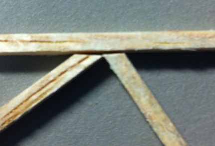
Here’s an unglued joint using 1/16” spars that were cut by hand. The gap you see at the top is a problem that’s hard to avoid. It’s there because the cut wasn’t made perfectly square to the spar. I can try sanding it square, but the chances of getting it perfect without reducing the length of the spar are slim.
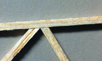
Here’s a very similar joint with spars cut using my balsa chopper. The difference is obvious. It’s easier to get accurate results using the tool than it is to get inaccurate results by hand.
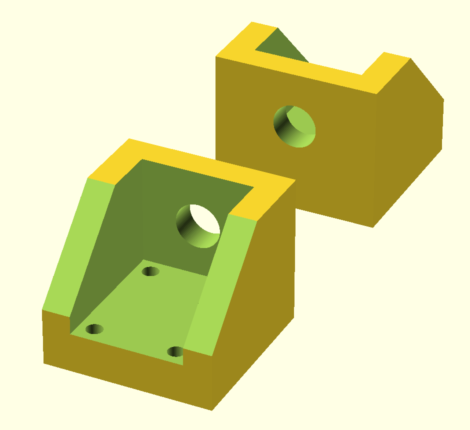
The tool consists of:
- four 3D printed ABS parts
- two skateboard wheel bearings
- an axle from a bicycle wheel hub
- four nuts for the axle
- eight sheet metal screws
- one length of 1/2” x 1/2” x 1/16” aluminum C-channel
- a chunk of particle board
- two socket head screws to lock the blade holder in place
- three tiny screws to hold the razor blade in place
- one razor blade
While the parts list seems a bit long, the entire thing is pretty simple.
This is probably the third iteration on this design that I’ve done. The first one used no 3D printed parts. It used a C-channel bar that was bolted to a chunk of MDF on one end, with a razor blade screwed directly to the C-channel bar.
The first iteration worked well aside from one annoying flaw: it was too easy for the blade to move side to side. There was too much play where the C-channel bolted to the hinge and very little could be done to fix that.
The second iteration used an all printed handle and skate (sometimes known as 608) bearings in the hinge. Despite using these bearings in my latest iteration, I’m not fully convinced they’re useful. The idea is that provide a solid point to pass an axle through and can be tightly pushed into a 3D printed part. If the axle has no play, and they’re tightly locked in a hinge, then the blade should also have no play.
The problem with the second iteration, primarily, was that I could never make it. Printing a part of that length is actually very difficult to do well.
ABS shrinks as it cools. If the part being printed has enough surface area, or in this case, just length, that shrinkage can cause the print to peel of the print bed. After several failed attempts I gave up.
The current design reduces the amount of plastic used. This reduces the number of attempts needed to get parts that work. It also lets me use the right kinds of materials for the right reasons. A C-channel handle is stronger and less likely to flex than a printed handle would be. It since I have a bunch just lying around, it’s much quicker to put it into use.
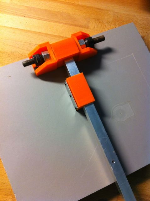
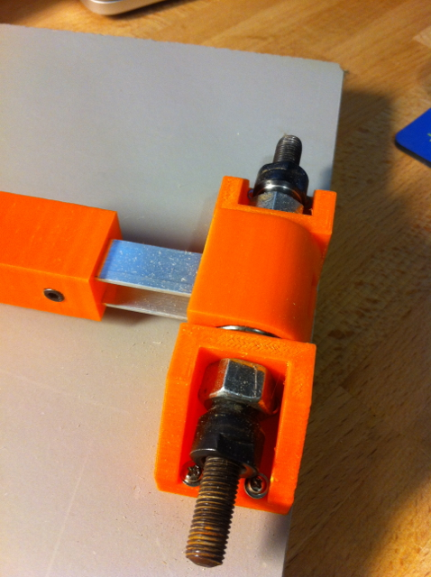
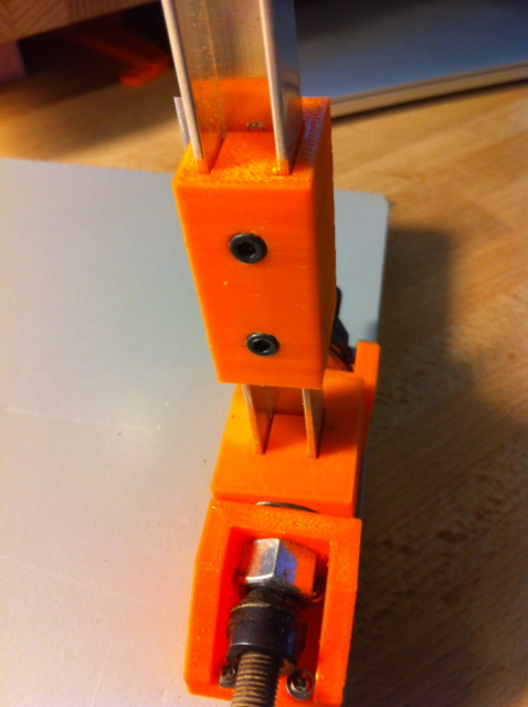
Here’s are some photos of the final design:
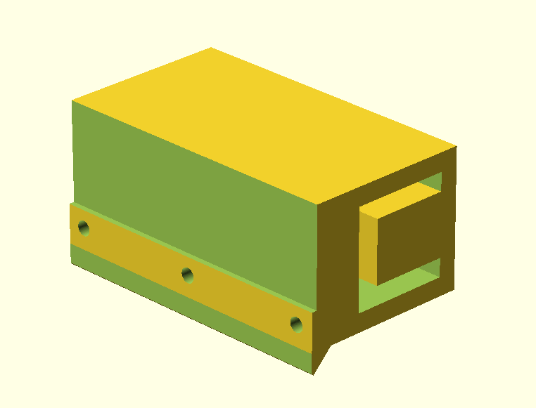
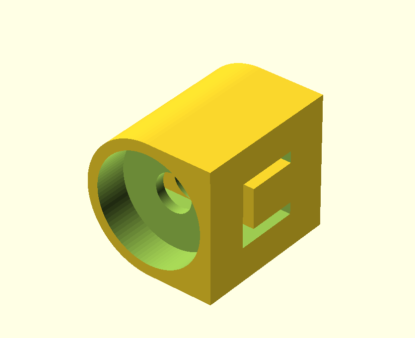
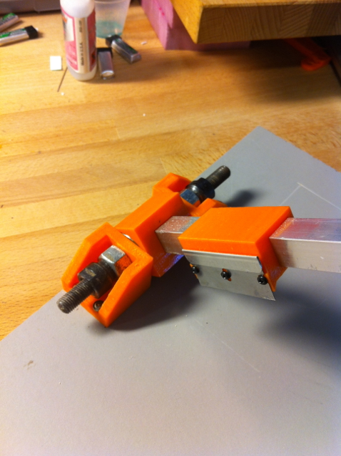
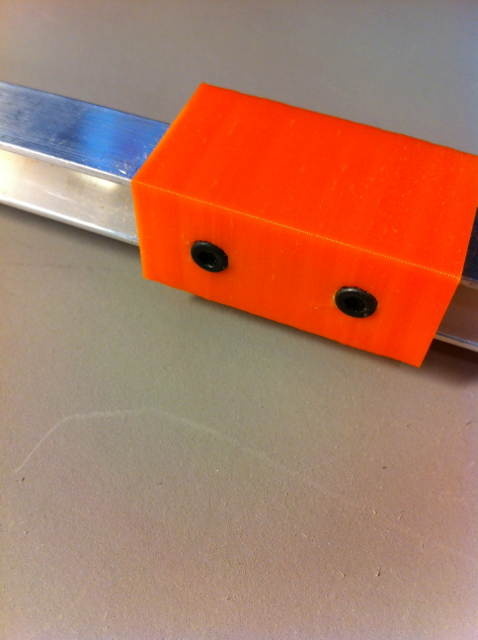
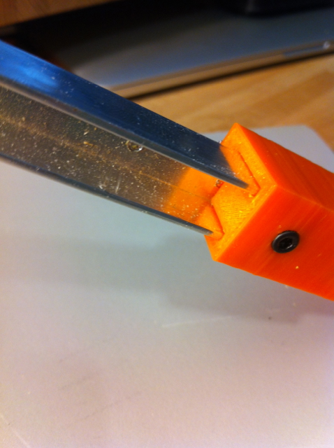
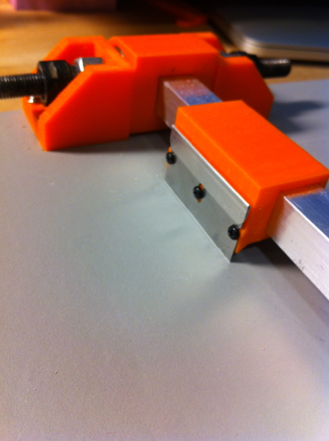
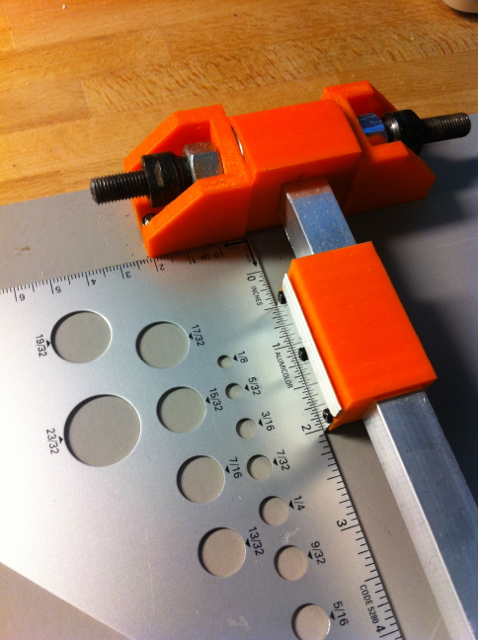
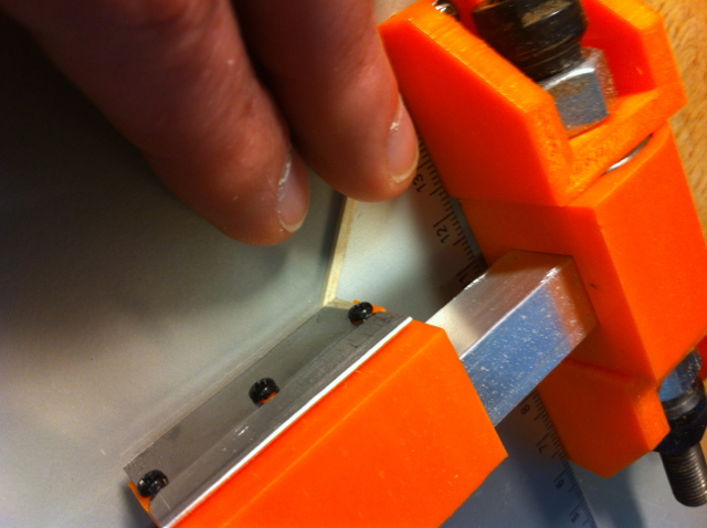
One thing I’m quite happy about is the blade holder. I didn’t plan it, but as it turns out the screws I’d intended to simply lock the blade holder to the handle can be loosened so that the holder can slide to any spot on the handle.
Being able to move the blade holder allows for a lot more versatility. I can cut parts at more extreme angles, or make cuts on wood that I wouldn’t normally be able to do because the blade is too close to the hinge.
Leaving the blade holder just loose enough to slide can allow me to use the chopper as a sort of radial arm saw. If I mount the blade so that one corner is slightly higher, I can make cuts that are longer than the blade itself.
For example, if the corner of the blade closest to me is raised, I can start a cut with the blade holder up against the hinge and pull towards me to make a perfectly square cut.
I was also planning on adding a straight edge up against the hinge similar to how I did it with my first iteration of this tool. But I’ve found I don’t need the straight edge. I’m usually just use a protractor to measure out the angles I need and tape or clamp an edge down.
I plan on designing blade holders that I can swap out as well. For example - I could have a blade holder that holds the blade at a 45 degree angle to the table. That’d allow me to make compound angle - one angle derived from the Z rotation of the part, the other derived from the X (or Y, I suppose) angle of the blade.
Want to make your own or improve upon my design?
Here’s a link to the source on Github. Here’s a link to the source and ready to slice STL files on Thingiverse.